Polishing Treatment for Plastic Molds
Polishing Treatment for Plastic Molds With the widespread application of plastic products, such as daily-use items and beverage packaging containers, there is often a requirement
We often find that the barrel wears a lot after production and use for a period of time. Like a screw, in order to meet the its working requirements, the barrel must be made of materials that are high-quality, high-temperature, wear-resistant, corrosion-resistant, and high-strength. These materials should also have good machinability and heat treatment properties.
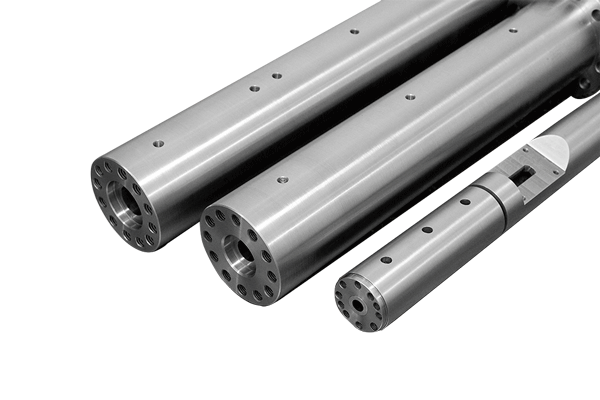
The barrel and screw constitute the extrusion system. The barrel also works under high pressure, high temperature, severe wear, and certain corrosion conditions. During the extrusion process, the barrel also can transfer heat to or away from the materials.
A heating and cooling system is also required on the barrel, and with a machine head installed.
In addition, a feeding port should be opened on the barrel. The geometry of the feeding port and the selection of its position have a great influence on the feeding performance. While the smoothness of the inner surface of the barrel and the opening of grooves on the inner wall of the feeding section have a great impact on the extrusion process. The above factors must be considered when designing or selecting the barrel.

In terms of the overall structure of the barrel, there are integral barrel and combined barrel.
It is processed on the whole blank. This structure is easy to ensure high manufacturing precision and assembly accuracy. It can also simplify the assembly work, facilitate the installation and assembly and disassembly of the heating and cooling system. Besides, the heat is relatively evenly distributed along the axial direction. Naturally, this kind of barrel requires higher processing and manufacturing conditions.
It is a barrel composed of several barrel sections. Experimental extruders and vented extruders mostly use combined barrels. The former is to facilitate changing the length of the barrel to adapt to the screw without a length-to-diameter ratio. While the latter is to set up an exhaust section. Stabilize product quality and reduce injection defects.
In a certain sense, the use of combined barrels is conducive to on-site material and processing, and is beneficial to small and medium-sized factories. But in fact, the combined barrel requires high machining accuracy. Each barrel section of the combined barrel is connected together with flange bolts. And this destroys the uniformity of the barrel heating and increases the heat loss. It is not convenient to set up and maintain the heating and cooling system.
In order to not only meet the material requirements of the barrel, but also save valuable materials, many barrels are lined with alloy steel bushings inside the base of general carbon steel or cast steel. After the bushing is worn out, it can be removed and replaced. The bushing and the barrel must be well matched to ensure that the heat conduction on the entire barrel wall is not affected. Meanwhile, the barrel and the bushing must not be able to move relative to each other, and they must be easily removed. It is necessary to select the appropriate fit precision for barrel.
A.Set longitudinal grooves on the inner wall of the feeding section of the barrel
To improve the solids conveying rate, it is known from the solids conveying theory that one method is to increase the coefficient of friction on the surface of the barrel. Another one is to increase the area of the material at the feeding port through the cross section perpendicular to the axis of the screw. The embodiments of these two methods:
The specific structure of opening a longitudinal groove or processing a taper at the feeding section of the barrel is as follows:
In general, the length of the taper can be (3~5)D (D is the inner diameter of the barrel). When processing powder, the taper can be extended to (6-10)D. The size of the taper depends on the diameter of the material particles and screw. When the screw diameter increases, the taper should be reduced (at the same time the length of the feeding section should be increased accordingly).
The longitudinal groove can only be opened on the section of the barrel before the material is still solid or begins to melt. The groove length is about (3-5) D, with a taper.
The number of grooves is related to the diameter of the screw. According to IKV, it is equivalent to about one-tenth of the diameter (cm) of the screw. Too many grooves will cause the material to flow back and reduce the conveying capacity. The shape of the groove can be rectangular, triangular, or other shapes. The width and depth of the groove with a rectangular cross-section are related to the diameter of the screw.
B. Forced cooling feeding section barrel
In order to increase the solids delivery, there is another method. It is to cool the feeding section barrel. And its purpose is to keep the temperature of the conveyed material below the softening point or melting point. Also, avoid the appearance of melt film, and maintain the solid friction properties of the material.
After adopting the above method, the transportation efficiency is increased from 0.3 to 0.6. Moreover, the extrusion volume is less sensitive to changes in die pressure.
However, this system also has the following disadvantages:
The shape of the feeding port and its opening position on the barrel have a great influence on the feeding performance. The feeding port should enable materials to be fed into the barrel freely and efficiently without bridging. In addition, the design should also consider the following problems:
The shape of the feeding port (top view) may be round, square, and rectangular. Generally, rectangular ones are used, the long side is parallel to the axis of the barrel. And its length is about 1.5-2 times the diameter of the screw.
Just like the screw, to meet the working requirements of the barrel, it must be made of high-quality materials with high temperature resistance, wear resistance, corrosion resistance and high strength. These materials should also have good machinability and heat treatment properties. In addition to the 45 steel, 40Cr, 38CrMoAL, the barrel can also be made of cast steel and ductile iron. The feeding section with bushing can be made of high-quality cast iron.
With the development of high-speed extrusion and engineering plastics, especially when extruding glass fiber reinforced plastics and plastics containing inorganic fillers, higher requirements are put forward for the abrasion and corrosion resistance of the barrel. Xaloy alloy developed by the United States, Belgium and other countries is a novel wear-resistant and corrosion-resistant material, and is currently widely used abroad.
The features of this material:
The method of its application to the barrel:
Heat this powdery Xaloy alloy and the barrel together at high temperature. Due to its low melting point, it can be melted into a fluid state at about 1200°C. The barrel rotates at a high speed, and the huge centrifugal force generated by the molten Xaloy makes it cast on the inner wall of the red hot barrel. Its thickness is about 2 mm. After cooling, it can be ground down by grinding about 0.20 mm.
A. The barrel wall thickness
The barrel is rarely scrapped due to insufficient strength, mainly due to corrosion and wear. The determination of the barrel wall thickness, in addition to the strength, the manufacturability and thermal inertia of the barrel structure should be considered more.
The wall thickness determined according to the latter two factors is often greater than the value calculated according to the strength conditions. Since there is no mature calculation method for calculating the wall thickness of the barrel according to the heat transfer characteristics of the barrel. Currently, most of the wall thickness is determined based on empirical statistics and analogy, and then the strength is checked.
B. Strength calculation
The strength calculation of the barrel is carried out according to the thick-walled barrel. No more discussion here.
Notice:

Polishing Treatment for Plastic Molds With the widespread application of plastic products, such as daily-use items and beverage packaging containers, there is often a requirement

Injection Molding Techniques for TPE and TPR Injection Molding Techniques for TPE and TPR 1. Dry the TPE and TPR material before injection molding It

Winter Maintenance Measures for Injection Molding Machines As winter approaches and temperatures gradually drop, a cold chill envelops the earth. While ensuring personal warmth, it

Assessment Regulations for Mold Trial Exceeding 3 Times Assessment Regulations for Mold Trial 1. Purpose The purpose of this regulation is to standardize the work of